HelixEdit User Guide
Introduction
Welcome to the HelixEdit User Guide! This guide provides a step-by-step instructions on using HelixEdit’s features, troubleshooting issues, and optimizing workflows.
Getting Started
This section covers how to install and set up HelixEdit for first-time users. It also introduces the main interface and navigation controls.
Requirements for the Tool
Quixel Bridge (latest version).
Maya 2023 or 2024.
About the Tool
Works with the latest MetaHuman updates.
Supports additional joints and expressions.
MetaHuman uses a different version of the weight map and makes adjustments for different body types. So, if you use anything other than the average male or female body type, an error may occur. To avoid this, simply select the default body type when exporting from MetaHuman Creator to Maya, and everything will work correctly. This step is not critical for later work, as you can create any body type within HelixEdit, and it won’t affect the process. However, ensuring the correct body type will help achieve a seamless neck seam.
The official MetaHuman Creator term is “Male/Female Average.” The issue is that this information isn’t stored in the DNA file, so we can’t determine which one you selected. Users often forget, as it’s typically a spur-of-the-moment choice.
Installation Steps
- Download & Extract
Download the tool and extract all files from the ZIP.


- Run the Installer
Open the folder and double-click the installation file.

- Accept Agreement
Read and agree to the terms to proceed.

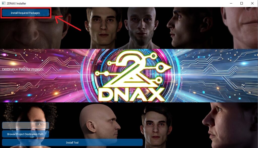
- Install Required Packages
The installer will prompt you to install Maya packages (these are required for the tool).
If needed, you can install them manually via Windows CMD.
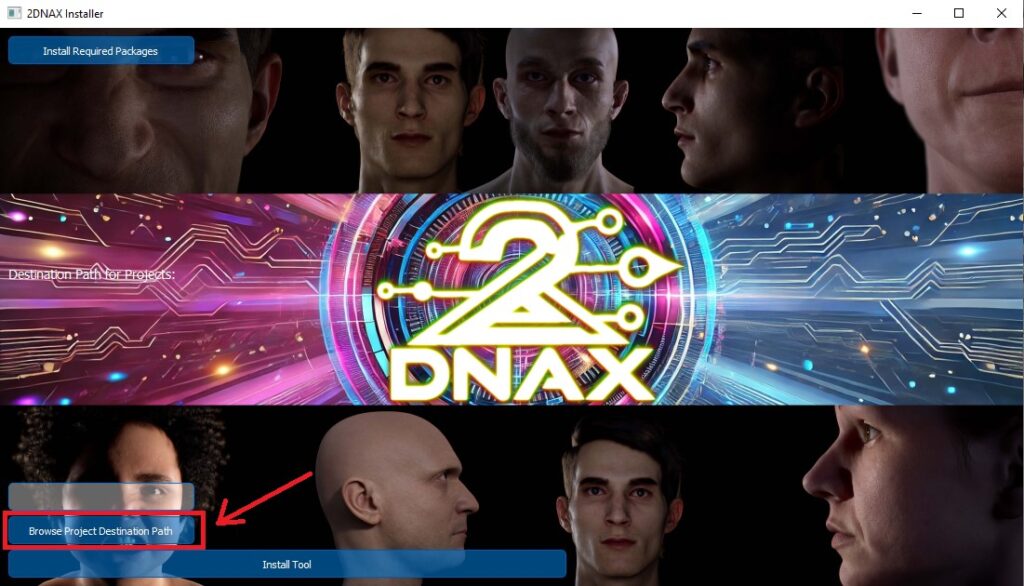
- Select Storage Location
Choose where character data (assets, DNA files, Maya scenes) will be stored.
Make sure there is enough space.
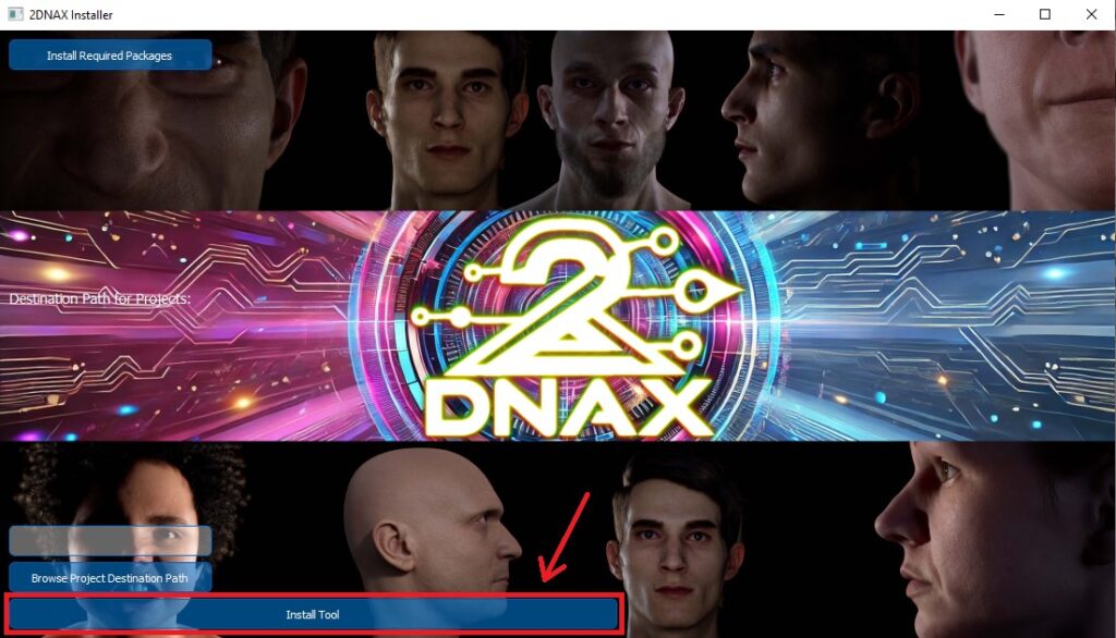
- Complete Installation
Click Install and wait for the process to finish.
The tool should now be ready inside Maya.
Activating the Tool in Maya
- Open Maya (2023/2024)
- Go to Window → Settings/Preferences → Plug-in Manager

- Find “2DNAX_plugin” and check:
Load
Auto Load (so it loads automatically every time)

- You will now see a dropdown menu next to the Help menu.

Introduction to the Main Interface and Navigation Controls
When you navigate to the 2DNAX Menu you can find two submenus: shapesModeling and Modeling.
In the shapesModeling submenu you can find Character Editor.

In the Modeling submenu you can find:
- Delta
- Import/Export
- Isolation_Tool
- Mesh_Normalize
- ExpressionBlending
- Toogle_Visibility

Core Features & Tools
HelixEdit provides a powerful set of tools for 3D character rigging and editing. Key features include:
- Character Editor
- Scene Access & Pipeline Integration
- Structured Folder Organization
- Character Management
- MetaHuman DNA File Compatibility
- Delta
- Import/Export
- Isolation_Tool
- Mesh_Normalize
- Toogle_Visibility
- ExpressionBlending
CharacterEditor
The first you can pick In the CharacterEditor are the project and the character you are working on by selecting them at the top (shown on the picture 13).

If you want to make a new project you can do that by typing in the Project name and Character name and pressing the Setup button.

When creating a character, you must choose between two options: BlendShape with Joints or BlendShape Only. This choice will determine the available options in the later stages of the pipeline.
For cinematic use, where only the highest LOD matters, BlendShape Only is the preferred option. However, if you’re working on a game character where LODs are crucial, BlendShape with Joints is the better choice.
If you select BlendShape with Joints, the Transfer Joints to Rig option will be unlocked in the character editor tab. This feature automatically calculates joint positions based on blendshape corrections for expressions. The calculation applies across all LODs automatically, but you can also adjust them manually if needed.
This ensures that the character’s likeness is preserved even at lower LODs, where using blendshapes might not be possible or practical.

If you want to rename the project you are working on, or the character, you can do that by typing in the new name and pressing the correct button. If you are renaming the project, press Rename Project button, and if you are renaming the character press the Rename Character button.
Important: In order to rename a project or a character, you need to select it first.

Retopology Tab
Before you begin, select your Topology and Scan_data meshes by clicking the appropriate mesh and then pressing the >>> button next to each corresponding field.
These meshes should be stabilized—meaning they should be positioned as closely aligned as possible, one on top of the other, just like in the example shown in images 18 and 19.
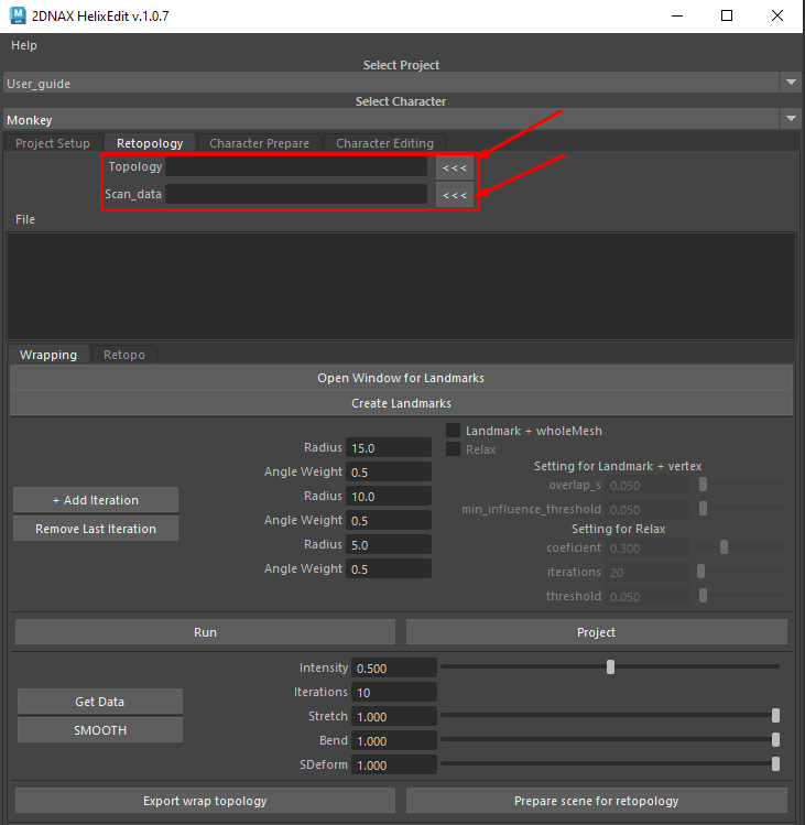
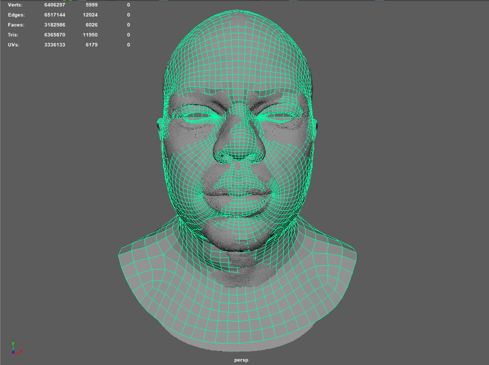
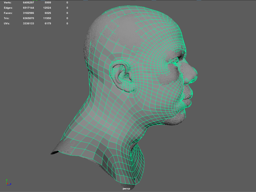
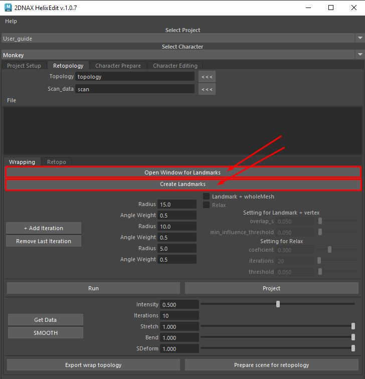
Once you have added the right meshes, you’ll need to add landmarks. You can do that by choosing the “Open Window for Landmarks” and after the window is open, choose “Create Landmarks”.
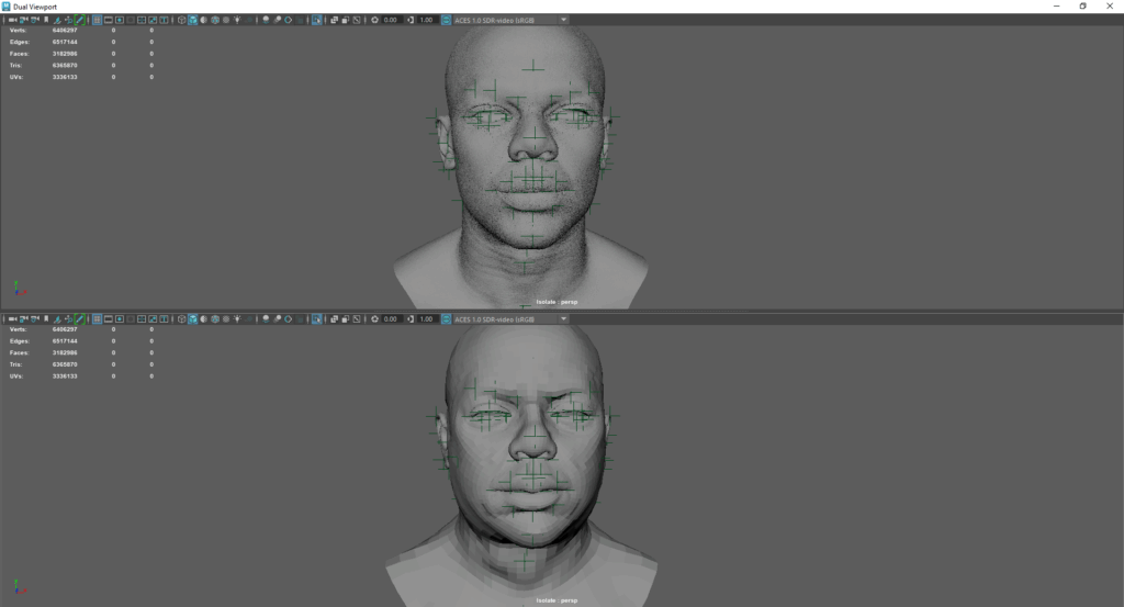
After this, you need to put the same number of Landmarks on both meshes. They need to be at the same place.
Note: Add one by one landmark, first on the scan, then on the topology mesh, after that again on the scan and retopology mesh, until you are satisfied with them.
Once you’re done with creating landmarks, you’ll need to choose the right iteration options. Once you’re done, choose the “Run” option. This will calculate and influence the retopology mesh to be closer to the scan. You can do this until you’re satisfied with the result.
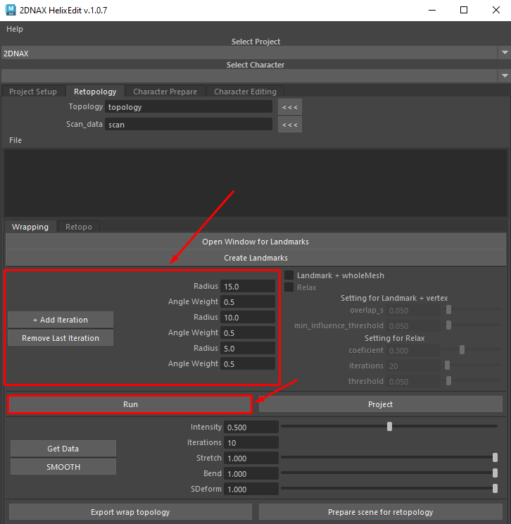
For best results, check both the “Landmark + Whole Mesh” options, along with the “Relax” setting. Adjust the values to fit your needs, and repeat the process until you’re satisfied. You can toggle certain settings on or off depending on what you’re trying to achieve.

Once you’re satisfied with results, you’ll need to import the paint map.
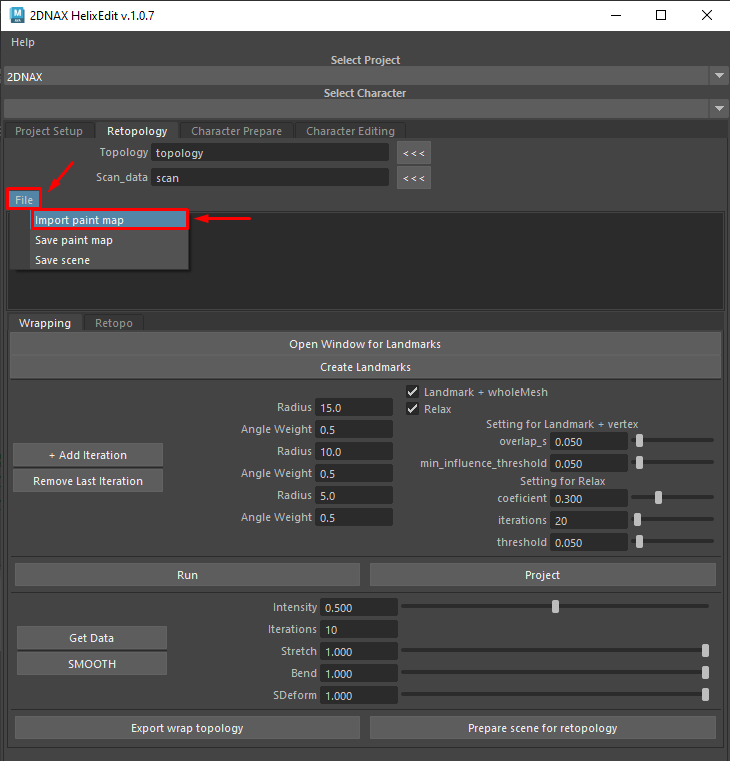
Once you chose the paint map, you need to go to Deform->Paint Weights->Blendshape, in order to see the map.
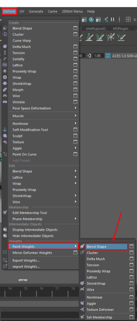
Here, you can adjust the map to fit your needs and meshes. White areas indicate what will be projected, while black areas represent what will be excluded. Additionally, you can save your own custom paint maps for later use.

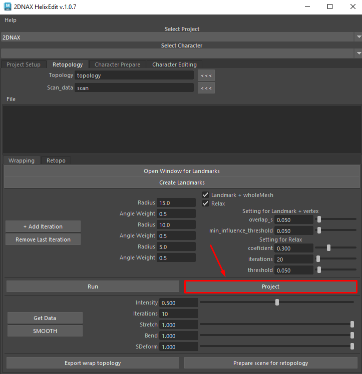
Once you’re done, choose the “Project” button to project mesh onto scan.

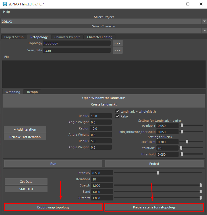
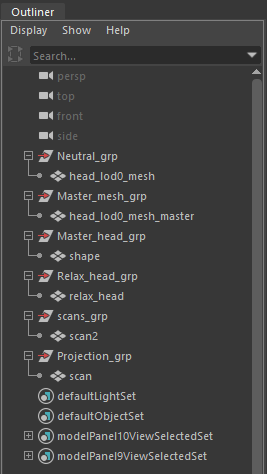
When you click “Prepare Scene for Retopology,” HelixEdit will automatically generate a scene tailored for the wrapping and retopology process. In the Outliner (left panel), you’ll see the following organized groups:
Neutral – Your current retopology mesh
Master Mesh – The original base mesh used at the start of the process plus master assets
Master Head – The original head mesh used for a blendshape from 0 to 39 frame
Relax Head – A duplicate of the Topology head used for Relaxing (you can replace this with any metahuman head with good topology)
Scans – The 3D scans/sculpt you’ve imported
Projection – Duplicate of the scan used for projecting
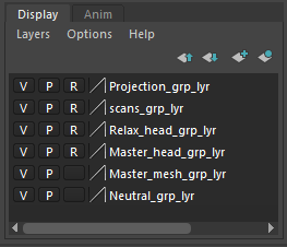
On the right side, it will make layers for each group and freeze what needs to be frozen so you can’t click on it accidentally.
A blendshape animation from frame 0 to 40 will be automatically created to streamline the retopology process. All adjustments should be made at frame 40, as frames 0 to 39 are frozen and not editable.
Character Prepare Tab
Before starting with character preparation you need to choose the project and the character you are working on. After this you need to place meshes in the correct folder: ‘\Projects\PROJECT_NAME\CHARACTER_NAME\BlendShapes\Neutral
Include the following files (if applicable):
- head_lod0_mesh
- body_lod0_mesh
- cartilage_lod0_mesh
- eyeEdge_lod0_mesh
- eyelashes_lod0_mesh
- eyeLeft_lod0_mesh
- eyeRight_lod0_mesh
- eyeshell_lod0_mesh
- saliva_lod0_mesh
- teeth_lod0_mesh
Important: The system can function without a body, but in that case, the head’s position will be determined by the selected height—male or female. The pipeline will fill in any missing assets from the provided DNA file, but they will not be automatically fitted. Instead, the pipeline will position them based on the DNA file’s character position. This means they may not align correctly if you have made edits to your custom character.
Issues can arise if you use a DNA file but only provide a head mesh in the folder without other necessary assets. It is crucial that all assets are positioned correctly to ensure that, once the rig is compiled, everything is in the right place.
One noticeable issue that can affect the rig is misaligned eyes—if the eyes are drastically out of place, the upper and lower eyelids will attempt to follow them, resulting in distorted blendshapes.
On the other hand, if you are using a character from MetaHuman Creator without any modifications, simply loading the DNA file will be sufficient, and everything will work correctly.
If a body is present, it will dictate the overall position and height. However, when clicking Body Prepare, it is crucial to select Male or Female, ensuring that the same choice is applied to both the body and the head.
Next, select Male or Female and press the Body Prepare button, making sure the selection is consistent for both the body and the head.

Once calculations are complete, click Save Body. Your Maya scene with the rigged body will be saved in the export folder.

If you want to use your own DNA file, you can do that by pressing the Choose DNA File button.

Set up the head: Use Editing mode for joint adjustments to refine neutral joint positions before finalizing.

Once editing mode is complete, you can review and adjust joint positions for all LODs. If you notice any errors, no matter how small or significant, you can make the necessary corrections during this stage. The automatic position is very accurate and works for all humanoid characters as it should, but in extreme cases such as monkeys, pigs and others, for better results you can manually correct all joints if need be (Preferred Workflow for AAA Characters).
Automatic joint positioning works exceptionally well with good topology and loopflow. However, if the topology is poor or the loops are misaligned—meaning key loops are placed incorrectly—it can result in strange deformations in the rig.
A proper retopology process is crucial for achieving good results. Pay special attention to important loops, such as:
- Eye crease
- Smile line
- Inner and outer vermilion
- Other key facial loops
Ensuring these loops are well-placed will significantly improve the rig’s accuracy and deformation quality.
Finalize the character: Click Prepare Character to generate the complete rig then Save before proceeding.
After preparing the character, the rig is ready. This is your final chance to review everything and check if the geometry needs adjustments. If necessary, you can manually edit it and save the changes.
When the Prepare Character is done, it will delete the body (which is what should happen), so that we can focus on working on the head and expressions. You can always import the body from the folder where it is saved to check how everything looks together, and in the case of exporting in further steps it will register the body from the folder and you don’t have to import it back in the scene.

Character Editing Tab
Now that you character is ready for work, simply refresh the selected character in the Character Editing tab to update it. Under the file, you will find your saved scene under the name character_prepared. That is the scene you are currently in.
A strong recommendation is to create a new scene so that this scene is not touched at all, so that you can always return to it and use the expressions in case something went wrong.

In order to manually edit the character you need to click the Setup Scene button.

Once you have done this, the Setup Scene button will no longer work, which indicates that the Setup Scene has been successfully done. It’s a good idea to save the scene now, so you won’t have to click this again the next time you open the character.
Save Scene button: You might select different components, such as eyes, scream, oh, head turns or final. After making your selections, click on the Save Scene button. This will save the current scene in the desired folder using the selected name.
You can also enter the name manually, and click Save Scene, and it will save it under that name. When you click Save Scene, you are saving the scene you created. If you need to save additional changes, you don’t always have to use a new name and then click Save Scene again. Instead, you can simply save the scene in Maya as usual by pressing Ctrl+S, which will save a new iteration under the same name.

Set Expression button: First, single left-click to select the desired expression from the branches. Once selected, click the Set Expression button. This action transfers the chosen expression to the middle (working) head, allowing you to blend it with the neutral pose or any other expression currently active on the rig head (last head on the right). This blending process helps you observe how the expression affects the vertices and ensures proper loop movement.
Double-clicking any expression in the branches will activate that expression on the rig head. Selecting an expression with a single left-click and confirming it with the Set Expression button transfers it to the working head, where it blends from 0 to 40. You should work only on the 40th frame, as it represents the final expression and its exact appearance. The blend always occurs between the rig head and the working head, based on their current states.
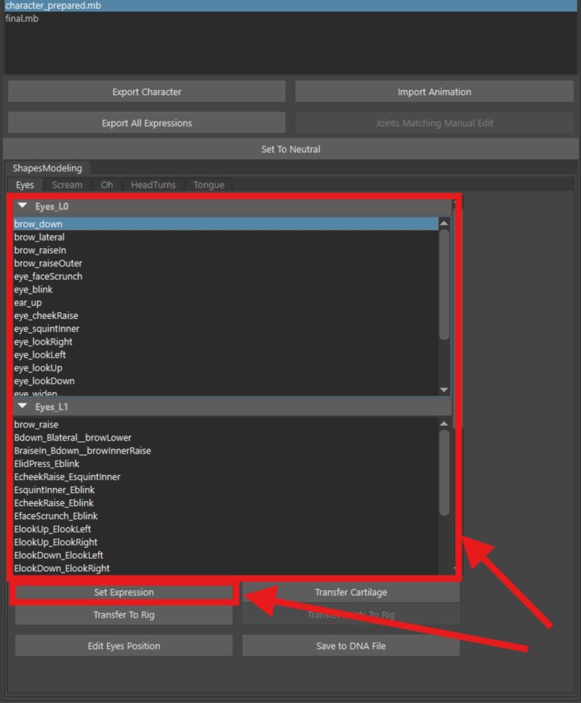
Transfer to Rig: Next, let’s manually edit the active brow down expression. By doing so, you can see how this modification influences other related expressions within the system. This connection ensures that changes are consistently applied across all relevant parts of the rig. Once you are satisfied with your edits, click on the Transfer to Rig button. You’ll notice that the changes affect not only the brow down expression, but also its combinations. This seamless integration maintains the coherence of your characters’ expressions.
A good way to check if you’ve transferred every detail to the rig is to blend your edited expression with the same expression on the rig. Double-click to apply it to the rig head—if sliding from 0 to 40th frame produces no change, it confirms a complete transfer.
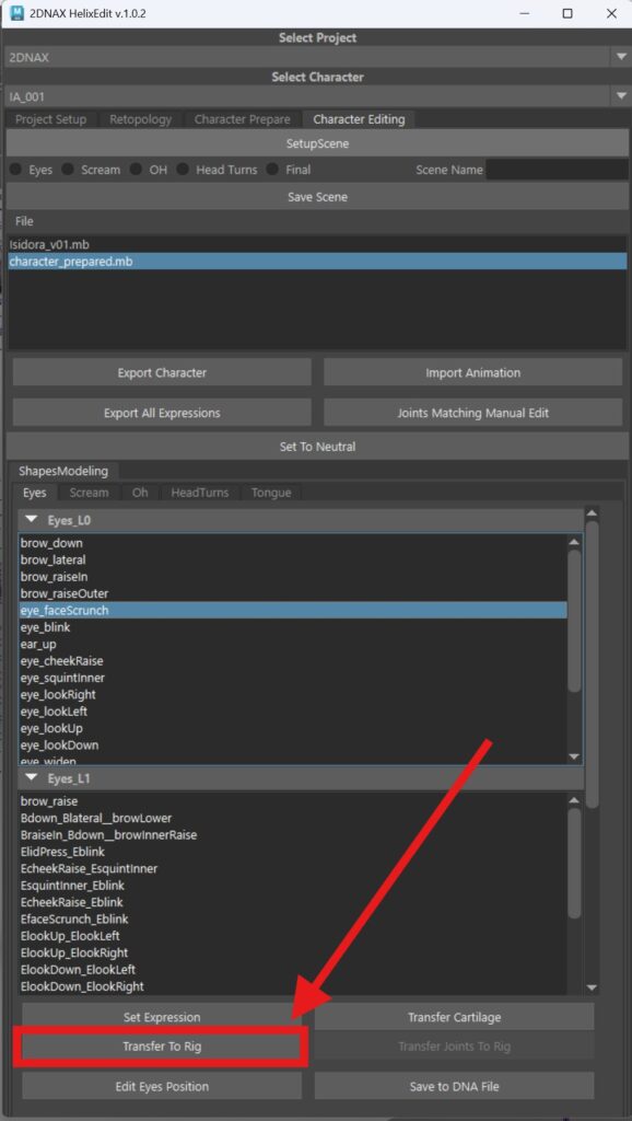
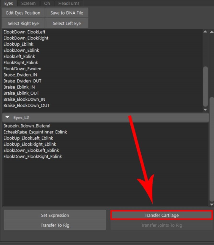
Transfer Cartilage: Only the eyes branch has the option for cartilage transfer because all changes in the eye region affect cartilage positioning. This process aligns vertices precisely and requires recalculation. When you click Transfer Cartilage, it will take a few seconds to compute the cartilage position for all eye expression.
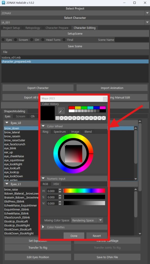
Color Coding System: You can select a specific expression and assign custom colors to it by right clicking on the expression and choosing Custom Color or any of the premade options like: Finished, Changed, Check. This feature allows expressions to stand out and ensure they remain prominent easy identifiable for future use.
This was designed to make it easier to track what has been completed and what still needs adjustments. We often mark approved expressions and focus on the remaining ones for a more convenient and efficient workflow. It also helps studios with multiple artists stay organized and track progress more effectively when working simultaneously.
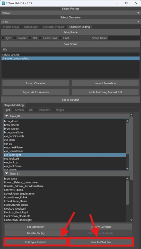
Edit Eye Position and Save to DNA File buttons:
This allows you to manually change the position of an eye and then save it to the DNA file.
The eye can only be adjusted within the Eyes branch using the Look Up, Look Left, Look Right, Look Down, or Blink expressions. First, set the desired expression, then hit the Edit Eyes Position button. This will apply the same expression to the rig, ensuring that when you move the eye on the working (middle) head, the rig head is influenced as well.
For expressions like Look Left and Look Right, custom characters often experience slight eye-popping issues. This feature provides a precise way to fix them. When enabled, adjusting the eye position on the working head will simultaneously update the rig head. Once satisfied with the positioning, save the changes by clicking Save to DNA File.
Important note: As you move the eye, you are actually modifying the joint position.
Export Character: An option to export a character. If exporting a full character (head + body), selecting male or female is unnecessary. If exporting only the head, choose Male/Female to ensure correct height. Use the same option as during setup for a proper export.
Marking all LODs exports 8 LODs for the head and 4 for the body.
Leaving it unmarked exports only the LOD0 cinematic mesh.
Finally, click Prepare for Export, then Export Character.
You can also export Anim Color Expression, and prepare the scene for animation in Maya and save.

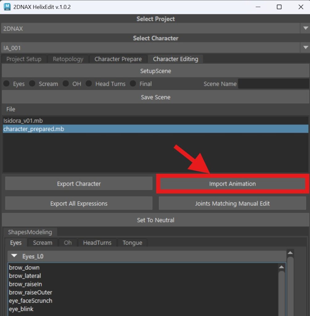
Import Animation: You can import animation on the character by choosing this button. You can choose some of the default animations or you can add your own.
Selecting Import Animation will open a window containing our standard test animation along with the FACS test animation, both used for testing and quickly reviewing all blendshapes for the character. Using this animation, you can efficiently assess how the blendshapes perform and identify which regions require the most attention.
Export All Expressions: Once you click Export All Expressions, you will receive 338 expressions, representing all possible combinations within the MetaHuman rig. While the rig itself contains over 700 expressions, this export provides combinations where the left and right sides form complete expressions. This approach enhances editing flexibility and ensures a seamless workflow.
You can find all these expressions in the character folder under blendshapes → objClean.
Joints Matching Manual Editing: When using the Blendshapes with Joints setup for a character, you have the option to manually adjust joints within the shapes if needed. The calculation is highly accurate, but if for any reason you need a different result, this feature allows you to make manual adjustments.
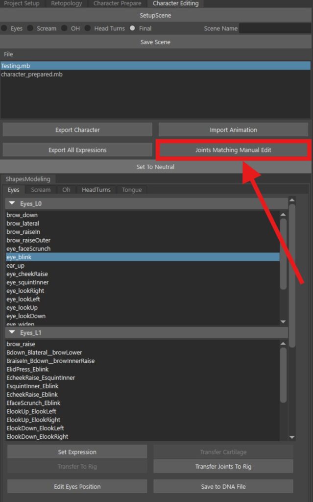
To begin, set the desired expression on the RIG head, then click the Joints Matching Manual Edit button. This will open a new window. First, you must disconnect the joints for the selected expression to manually modify them. Once disconnected, the joints will be color-coded in both the layers and viewport for easier navigation. They are also isolated so you can clearly see which joints correspond to each LOD. This part is done on the RIG HEAD.
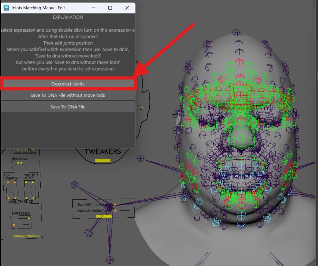
- Gray joints influence multiple LODs simultaneously.
- After making the necessary adjustments, you have two saving options:
- Save to DNA file without moving LOD0 – Use this when you only need to adjust lower LODs while keeping LOD0 unchanged.
- Save to DNA file – Saves all changes, including modifications to LOD0.
This flexibility ensures you can fine-tune your character while maintaining control over different levels of detail.
Set to Neutral: This button will set the RIG head to neutral expression.
Delta
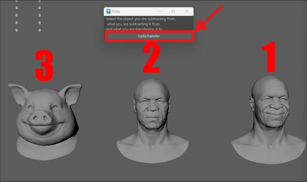
With the Delta tool, you can quickly create high-end expressions and isolate specific ones from combinations. It requires three head models to work and is compatible with humanoid characters as well.
In our example, we’ll transfer an expression from a custom MetaHuman character to our PIG MetaHuman without any manual adjustments.
- Copy the neutral expression of the character you’re transferring the expression from.
- Select the desired expression to transfer (in this case, mouth_cornerPull).
- Copy the neutral head of the PIG MetaHuman, which will receive the expression.
Now, select the heads in the following order:
- The expression from the original character (mouth_cornerPull).
- The neutral version of that same character.
- The target character receiving the expression.
Finally, hit the Delta Transfer button, and the expression will be applied automatically.
Import/Export
This tool is providing a way to import or export a mesh.
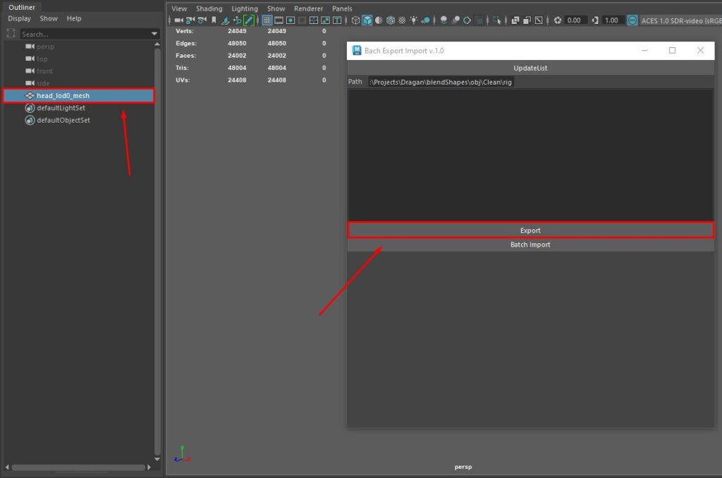
In order to import a mesh, you need to choose the path to it, and then press the button Update List (picture 50). Your meshes from the folder should be listed below. In order to import you need to double click on mesh to import, or choose the Batch Import (picture 51) button.


If you want to export a mesh, you need to select it first and then in the Import/Export tool choose the Export button.
Isolation_Tool
Isolation tool is used when you want to isolate a part of a mesh in order to do a better retopology or something else.
In order to use the Isolation_Tool, you need to select a retopo mesh and then press the <<< button on the right of retopo field. Do the same for master mesh, but press the <<< button on the right of the master field.

In order to isolate something you need to choose the right button below.

Mesh_Normalize
Mesh_Normalize is mostly used in the retopology process, where your loops are going into direction of a master shape where the retopology is already done.
In order to use the Mesh_Normalize you need to select the master mesh first, where the retopology is already done. After that, you need to add the master data to the tool by pressing the button MasterData.

From here, you can either type in the iteration and choose MasterNormalize button, where the selected vertices are going to take the master vertices’ position based on the number of iteration (picture 56), or you can choose SetToMaster button, where selected vertices are going to take the master vertices’ position all the way (picture 57).


Toggle_Visibility
Toggle_Visibility is allowing us to toggle between two or more meshes made into layers, which can be very useful when you want to compare those meshes.
In order to use Toggle_Visibility you need to choose layers you want and input their names. You have fields for 5 layers’ names. By pressing the Toggle Layers button, you can now toggle between them by pressing ` shortcut on the keyboard.

Troubleshooting & FAQs
Common issues and their solutions are covered here, including:
– Installation Errors
– Rigging Errors
– File Compatibility Issues
– Performance Optimization Tips
– UnrealEngine implementation
– FAQ
Installation Errors
If the required packages are not installed, you’ll need to install them manually. Here’s how:
- Open Command Prompt as Administrator.
- Navigate to the Maya bin folder. Replace MayaVersion with your version (2023/2024):
cd C:\Program Files\Autodesk\Maya2023\bin
- Install each package using Mayapy. Run the following commands one by one:
mayapy -m pip install orjson
mayapy -m pip install scipy
mayapy -m pip install requests
mayapy -m pip install py-machineid
mayapy -m pip install numpy
mayapy -m pip install pymel
mayapy -m pip install msgpack
- Verify Installation:
- After installing all the packages, you can verify their installation by running:
mayapy -m pip list
- This will display a list of installed packages, and you should see the ones you just installed.
Repeat this process for each package listed above. Once all packages are installed, the tool should work as expected.
Verify Installation Example:
- After installing all the packages, you can verify their installation by running:“`cmd mayapy -m pip list

The most reliable variant is, while updating the tool manually, to click on install packages again, so that it checks whether all packages are installed. During the release, some additional packages may be added that were not there in the initial version.
The tool is automatically installed on the c partition, which sometimes requires admin privileges, so it is not always able to transfer everything necessary for the tool to work. This is a frequent occurrence with studios or users who have custom settings for the system. In that case it is necessary to check the config_file (in the folder where it is installed on c), if it is not there, it should be transferred manually (picture 60). And you should correct the project path and tool path, replace them with your paths. (picture 61)


DNA File – rl4Embedded_Archetype
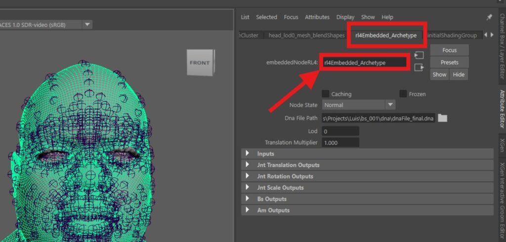
If using a custom DNA file, HelixEdit will not detect it automatically. To ensure proper functionality, set up the character, click on the RIG head, and verify the naming. The name must match the reference image exactly—if not, rename it accordingly.
DNA File Location
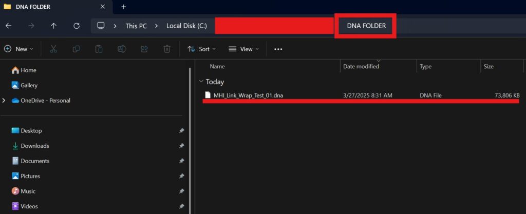
Store your DNA files in a separate folder, away from other assets. The folder can be located anywhere, but it must not contain any additional OBJ files.
FAQ
Character Management
💬 What can I do with Character Management?
You can rename, create, load, or delete characters directly within the tool, streamlining workflow and organization.
Joint Position Editing
💬 Why is joint position editing important?
It allows you to fine-tune joint placement for better deformation and animation accuracy, ensuring your character moves naturally.
Scene Preparation
💬 What does Scene Preparation do?
The tool automatically sets up the scene for character workflows, saving time and reducing manual setup errors.
Automatic Neutral Joint Calculation
💬 How does this feature improve character rigging?
It automates neutral joint placement for humanoid characters, improving default poses and reducing manual adjustments.
Blendshape Management
💬 How does Blendshape Management help?
You can adjust blendshapes directly on the rig, making it easier to refine facial expressions and movements.
Automatic Calculation
💬 What does automatic calculation do?
It automates joint position adjustments in blendshapes, reducing manual effort while maintaining accuracy.
Eye Position Adjustment
💬 Why would I manually adjust eye positions?
Even with automation, manual fine-tuning allows for greater realism and alignment with scanned or reference data.
Cartilage Calculation
💬 What is cartilage calculation used for?
The tool automatically positions cartilage areas, improving natural movement and secondary deformations in animations.
Color Coding System
💬 How does the color coding system help?
It visually organizes layers and components, making it easier to navigate complex character structures.
Mesh Normalize
💬 What is Mesh Normalize?
This feature corrects loop flow, ensuring smooth deformation and seamless animation for realistic character movement.
Isolation Tool
💬 What does the Isolation Tool do?
It allows you to focus on specific face regions, making precise edits without affecting the rest of the mesh.
Blending Tool
💬 How does the Blending Tool work?
It enables real-time shape blending, letting you check how different shapes interact dynamically.
Toggle Tool
💬 What is the Toggle Tool for?
It helps manage layers efficiently, allowing you to troubleshoot and isolate issues quickly.
Best Practices & Workflow Tips
To maximize efficiency when using HelixEdit:
– Use the structured folder organization
– Leverage automation for joint positioning
– Regularly save DNA files for backup
– Use hotkeys for Toggle Layers and Mesh Normalize
Tips and Tricks
Setting Up a Hotkey for MeshNormalize in Maya
Creating a hotkey for MeshNormalize can significantly speed up your workflow. Follow these steps to set it up:
- Copy the Shortcut
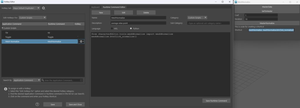
At the bottom of the MeshNormalize tool, you’ll find a shortcut (highlighted in blue in the image).
Copy this shortcut.
- Open the Hotkey Editor
Navigate to Windows → Settings/Preferences → Hotkey Editor.
- Create a New Runtime Command
In the Hotkey Editor, locate the Runtime Command Editor section.
Click New to create a new command.
Enter a Name and Description that will help you identify the hotkey later.
Important: Set the Language to Python.
Paste the copied shortcut into the empty field below the language selection.
Click Save Runtime Command.
- Assign a Hotkey
Now that the command is saved, you can assign a key to it.
This allows you to quickly trigger MeshNormalize with a single key press, boosting your efficiency.
By following these steps, you can streamline your workflow and reduce the time spent navigating menus.
Setting Up a Hotkey for Toggle Layers in Maya
Creating a hotkey for MeshNormalize can significantly speed up your workflow. Follow these steps to set it up:
- Copy the Shortcut
At the bottom of the Toggle Layers tool, you’ll find a shortcut (highlighted red in the image).
Copy this shortcut.
- Open the Hotkey Editor
Navigate to Windows → Settings/Preferences → Hotkey Editor.
- Create a New Runtime Command
In the Hotkey Editor, locate the Runtime Command Editor section.
Click New to create a new command.
Enter a Name and Description that will help you identify the hotkey later.
Important: Set the Language to Python.
Paste the copied shortcut into the empty field below the language selection.
Click Save Runtime Command.
- Assign a Hotkey
Now that the command is saved, you can assign a key to it.
This allows you to quickly trigger Toggle Layers with a single key press, boosting your efficiency.
By following these steps, you can streamline your workflow and reduce the time spent navigating menus.
